- 您现在的位置:买卖IC网 > Sheet目录3887 > PIC16F785-I/SS (Microchip Technology)IC PIC MCU FLASH 2KX14 20SSOP
143
8272E–AVR–04/2013
ATmega164A/PA/324A/PA/644A/PA/1284/P
17. 8-bit Timer/Counter2 with PWM and asynchronous operation
17.1
Features
Single channel counter
Clear Timer on Compare Match (Auto Reload)
Glitch-free, phase correct Pulse Width Modulator (PWM)
Frequency generator
10-bit clock prescaler
Overflow and Compare Match Interrupt Sources (TOV2, OCF2A and OCF2B)
Allows clocking from external 32kHz watch crystal independent of the I/O clock
17.2
Overview
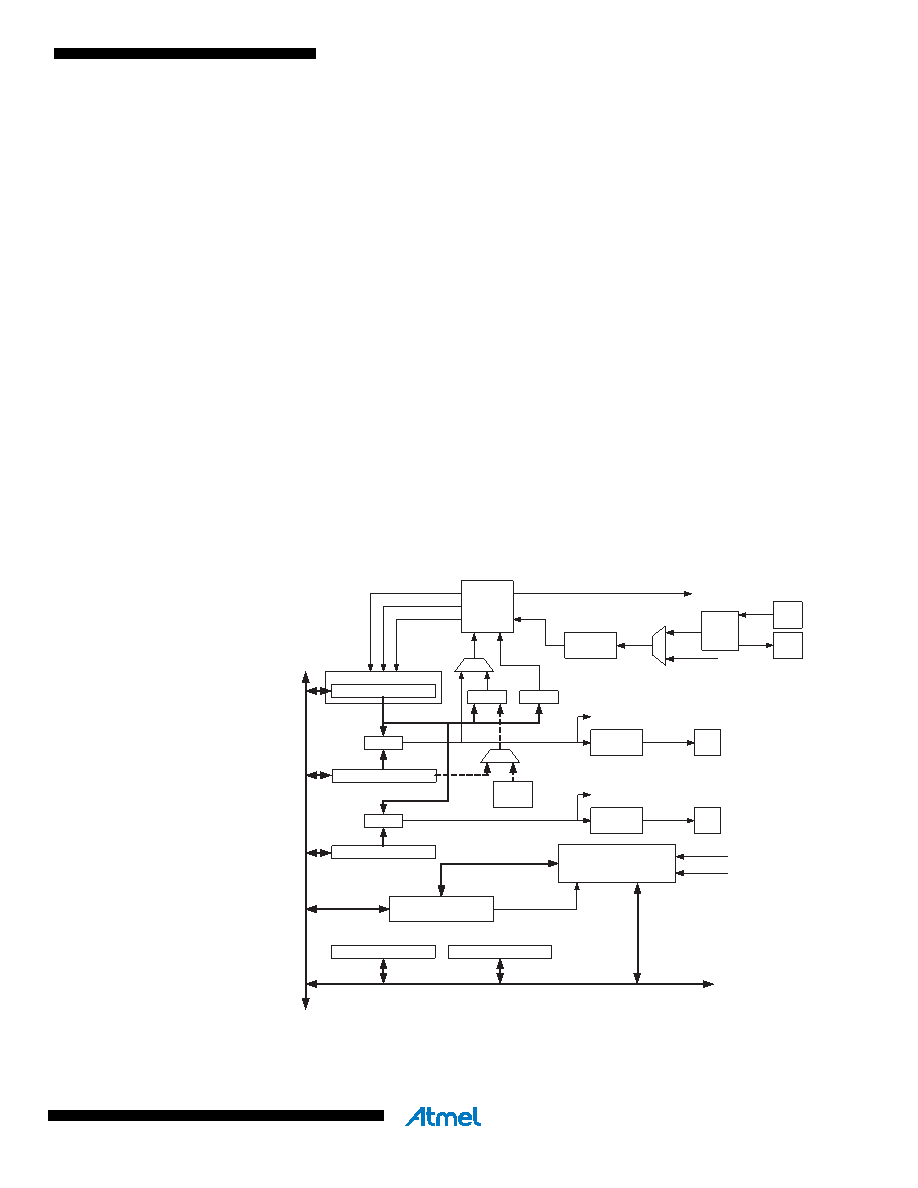
Timer/Counter2 is a general purpose, single channel, 8-bit Timer/Counter module.
A simplified block diagram of the 8-bit Timer/Counter is shown in Figure 16-12.. For the actual
placement of I/O pins, see ”Pin configurations” on page 2. CPU accessible I/O Registers, includ-
ing I/O bits and I/O pins, are shown in bold. The device-specific I/O Register and bit locations
are listed in the ”Register description” on page 157.
The Power Reduction Timer/Counter2 bit, PRTIM2, in ”PRR0 – Power Reduction Register 0” on
page 48 must be written to zero to enable Timer/Counter2 module.
Figure 17-1. 8-bit Timer/Counter block diagram.
Timer/Counter
DA
T
A
B
U
S
OCRnA
OCRnB
=
TCNTn
Waveform
Generation
Waveform
Generation
OCnA
OCnB
=
Fixed
TOP
Value
Control Logic
= 0
TOP
BOTTOM
Count
Clear
Direction
TOVn
(Int.Req.)
OCnA
(Int.Req.)
OCnB
(Int.Req.)
TCCRnA
TCCRnB
clk
Tn
ASSRn
Synchronization Unit
Prescaler
T/C
Oscillator
clk
I/O
clk
ASY
asynchronous mode
select (ASn)
Synchronized Status flags
TOSC1
TOSC2
Status flags
clk
I/O
发布紧急采购,3分钟左右您将得到回复。
相关PDF资料
PIC16C433T-I/SO
IC MCU CMOS 8BIT 10MHZ 2K 18SOIC
PIC16C773T-E/SO
IC MCU OTP 4KX14 A/D PWM 28SOIC
PIC16CE623T-30/SO
IC MCU OTP 512X14 EE COMP 18SOIC
PIC16F1825-E/ML
MCU PIC 14K FLASH 1K RAM 16QFN
PIC16F1828-I/SO
IC PIC MCU 8BIT 14KB FLSH 20SOIC
PIC16F688-I/SL
IC PIC MCU FLASH 4KX14 14SOIC
22-02-3213
CONN FFC/FPC VERTICAL 21POS .100
22-15-3193
CONN FFC/FPC 19POS .100 RT ANG
相关代理商/技术参数
PIC16F785T-E/SS
功能描述:8位微控制器 -MCU 3.5KB FL 128R 18 I/O RoHS:否 制造商:Silicon Labs 核心:8051 处理器系列:C8051F39x 数据总线宽度:8 bit 最大时钟频率:50 MHz 程序存储器大小:16 KB 数据 RAM 大小:1 KB 片上 ADC:Yes 工作电源电压:1.8 V to 3.6 V 工作温度范围:- 40 C to + 105 C 封装 / 箱体:QFN-20 安装风格:SMD/SMT
PIC16F785T-I/ML
功能描述:8位微控制器 -MCU 3.5 KB 128 RAM 18I/O RoHS:否 制造商:Silicon Labs 核心:8051 处理器系列:C8051F39x 数据总线宽度:8 bit 最大时钟频率:50 MHz 程序存储器大小:16 KB 数据 RAM 大小:1 KB 片上 ADC:Yes 工作电源电压:1.8 V to 3.6 V 工作温度范围:- 40 C to + 105 C 封装 / 箱体:QFN-20 安装风格:SMD/SMT
PIC16F785T-I/ML036
制造商:Microchip Technology Inc 功能描述:
PIC16F785T-I/ML045
制造商:Microchip Technology Inc 功能描述:
PIC16F785T-I/SO
功能描述:8位微控制器 -MCU 3.5KB FL 128R 18 I/O RoHS:否 制造商:Silicon Labs 核心:8051 处理器系列:C8051F39x 数据总线宽度:8 bit 最大时钟频率:50 MHz 程序存储器大小:16 KB 数据 RAM 大小:1 KB 片上 ADC:Yes 工作电源电压:1.8 V to 3.6 V 工作温度范围:- 40 C to + 105 C 封装 / 箱体:QFN-20 安装风格:SMD/SMT
PIC16F785T-I/SS
功能描述:8位微控制器 -MCU 3.5KB FL 128R 18 I/O RoHS:否 制造商:Silicon Labs 核心:8051 处理器系列:C8051F39x 数据总线宽度:8 bit 最大时钟频率:50 MHz 程序存储器大小:16 KB 数据 RAM 大小:1 KB 片上 ADC:Yes 工作电源电压:1.8 V to 3.6 V 工作温度范围:- 40 C to + 105 C 封装 / 箱体:QFN-20 安装风格:SMD/SMT
PIC16F818-E/ML
功能描述:8位微控制器 -MCU 1.75KB 128RAM 16 I/O Ext Temp QFN28 RoHS:否 制造商:Silicon Labs 核心:8051 处理器系列:C8051F39x 数据总线宽度:8 bit 最大时钟频率:50 MHz 程序存储器大小:16 KB 数据 RAM 大小:1 KB 片上 ADC:Yes 工作电源电压:1.8 V to 3.6 V 工作温度范围:- 40 C to + 105 C 封装 / 箱体:QFN-20 安装风格:SMD/SMT
PIC16F818-E/P
功能描述:8位微控制器 -MCU 1.75KB 128RAM 16 I/O Ext Temp PDIP18 RoHS:否 制造商:Silicon Labs 核心:8051 处理器系列:C8051F39x 数据总线宽度:8 bit 最大时钟频率:50 MHz 程序存储器大小:16 KB 数据 RAM 大小:1 KB 片上 ADC:Yes 工作电源电压:1.8 V to 3.6 V 工作温度范围:- 40 C to + 105 C 封装 / 箱体:QFN-20 安装风格:SMD/SMT